|
|

 |
|
|
|
|
 |
New York
Architecture Images- Midtown IRT Powerhouse |
|||||
|
architect |
McKim, Mead and White/ Solomon Deyo/ Walker O. Cain | |||||
|
location |
Eleventh Ave., at W58. | |||||
|
date |
1904 | |||||
|
style |
Renaissance Revival | |||||
|
construction |
brick facade | |||||
|
type |
Utility | |||||
|
|
||||||
|
notes |
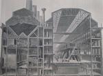
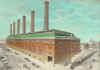
 Exterior View of Power House (Hand-tinted illustration.)
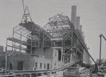
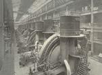
The type of power house adopted provides for a single row of large engines and electric generators, contained within an operating room placed beside a boiler house, with a capacity of producing, approximately, not less than 100,000 horse power when the machinery is being operated at normal rating. Location and General Plan of Power HouseThe work of preparing the detailed plans of the power house structure was, in the main, completed early in 1902, and resulted in the present plan, which may briefly be described as follows. The structure is divided into two main parts - an operating room and a boiler house, with a partition wall between the two sections. The face of the structure on Eleventh Avenue is 200 feet wide, of which width the boiler house takes 83 feet and the operating section 117 feet. The operating room occupies the northerly side of the structure and the boiler house the southerly side. The designers were enabled to employ a contour of roof and wall section for the northerly side that was identical with the roof and wall contour of the southerly side, so that the building, when viewed from either end, presents a symmetrical appearance with both sides of the building alike in form and design. The operating room section is practically symmetrical in its structure, with respect to its center; it consists of a central area, with a truss roof over same along with galleries at both sides. The galleries along the northerly side are primarily for the electrical apparatus, while those along the southerly side are given up chiefly to the steam-pipe equipment. The boiler room section is also practically symmetrical with respect to its center. A sectional scheme of the power house arrangement was determined on, by which the structure was to consist of five generating sections, each similar to the others in all its mechanical details; but, at a later date, a sixth section was added, with space on the lot for a seventh section. Each section embraces one chimney along with the following generating equipment: twelve boilers, two engines, each direct connected to a 5,000 kilowatt alternator; two condensing equipments, two boiler-feed pumps, two smoke-flue systems, and detail apparatus necessary to make each section complete in itself. The only variation is the turbine plant hereafter referred to. In addition to the space occupied by the sections, an area was set aside, at the Eleventh Avenue end of the structure, for the passage of the railway spur from the New York Central tracks. The total length of the original five-section power house was 585 feet 9.5 inches, but the additional section afterwards added makes the over all length of the structure 693 feet 9.75 inches. In the fourth section it was decided to omit a regular engine with its 5,000 kilowatt generator, and in its place substitute a 5,000 kilowatt lighting and exciter outfit. Arrangements were made, however, so that this outfit can afterward be replaced by a regular 5,000 kilowatt traction generator. The plan of the power station included a method of supporting the chimneys on steel columns, instead of erecting them through the building, which modification allowed for the disposal of boilers in spaces which would otherwise be occupied by the chimney bases. By this arrangement it was possible to place all the boilers on one floor level. The economizers were placed above the boilers, instead of behind them, which made a material saving in the width of the boiler room. This saving permitted the setting aside of the aforementioned gallery at the side of the operating room, closed off from both boiler and engine rooms, for the reception of the main-pipe systems and for a pumping equipment below it. The advantages of the plan can be enumerated briefly as follows: The main engines, combined with their alternators, lie in a single row along the center line of the operating room with the steam or operating end of each engine facing the boiler house and the opposite end toward the electrical switching and controlling apparatus arranged along the outside wall. Within the area between the boiler house and operating room there is placed, for each engine, its respective complement of pumping apparatus, all controlled by and under the operating jurisdiction of the engineer for that engine. Each engineer has thus full control of the pumping machinery required for his unit. Symmetrically arranged with respect to the center line of each engine are the six boilers in the boiler room, and the piping from these six boilers forms a short connection between the nozzles on the boilers and the throttles on the engine. The arrangement of piping is alike for each engine, which results in a piping system of maximum simplicity that can be controlled, in the event of difficulty, with a degree of certainty not possible with a more complicated system. The main parts of the steam-pipe system can be controlled from outside this area. The single tier of boilers makes it possible to secure a high and well ventilated boiler room with ventilation into a story constructed above it, aside from that afforded by the windows themselves. The boiler room will therefore be cool in warm weather and light, and all difficulties from escaping steam will be minimized. In this respect the boiler room will be superior to corresponding rooms in plants of older construction, where they are low, dark, and often very hot during the summer season. The placing of the economizers, with their auxiliary smoke flue connections, in the economizer room, all symmetrically arranged with respect to each chimney, removes from the boiler room an element of disturbance and makes it possible to pass directly from the boiler house to the operating room at convenient points along the length of the power house structure. The location of each chimney in the center of the boiler house between sets of six boilers divides the coal bunker construction into separate pockets by which trouble from spontaneous combustion can be localized, and, as described later, the divided coal bunkers can provide for the storage of different grades of coal. The unit basis on which the economizer and flue system is constructed will allow making repairs to any one section without shutting off the portions not connected directly to the section needing repair. The floor of the power house between the column bases is a continuous mass of concrete nowhere less than two feet thick. The massive concrete foundations for the reciprocating engines contain each 1,400 yards of concrete above mean high water level, and in some cases have twice as much below that point. The total amount of concrete in the foundations of the finished power house is about 80,000 yards. Water for condensing purposes is drawn from the river and discharged into it through two monolithic concrete tunnels parallel to the axis of the building. The intake conduit has an oval interior, 10 x 84 feet in size, and a rectangular exterior cross-section; the outflow tunnel has a horseshoe-shape cross-section and is built on top of the intake tunnel. These tunnels were built throughout in open trench, which, at the shore end, was excavated in solid rock. At the river end the excavation was, at some places, almost entirely through the fill and mud and was made in a cofferdam composed chiefly of sheet piles. As it was impossible to drive these piles across the old timber crib which formed the old dock front, the latter was cut through by a pneumatic caisson of wooden-stave construction, which formed part of one side of the cofferdam. At the river end of the cofferdam the rock was so deep that the concrete could not be carried down to its surface, and the tunnel section was built on a foundation of piles driven to the rock and cut off by a steam saw 19.5 feet below mean hightide. This section of the tunnel was built in a 65 x 48-foot floating caisson 24 feet deep. The concrete was rammed in it around the moulds and the sides were braced as it sunk. After the tunnel sections were completed, the caisson was sunk, by water ballast, to a bearing on the pile foundation. Adjacent to the condensing water conduits is the 10 x 15-foot rectangular concrete tunnel, through which the underground coal conveyor is installed between the shore end of the pier and the power house. Steel WorkThe steel structure of the power house is independent of the walls, the latter being self-supporting and used as bearing walls only for a few of the beams in the first floor. Although structurally a single building, in arrangement it is essentially two, lying side by side and separated by a brick division wall. There are 58 transverse and 9 longitudinal rows of main columns, the longitudinal spacing being 18 feet and 36 feet for different rows, with special bracing in the boiler house to accommodate the arrangement of boilers. The columns are mainly of box section, made up of rolled or built channels and cover plates. They are supported by cast-iron bases, resting on the granite capstones of the concrete foundation piers. Both the boiler house and the engine house have five tiers of floor framing below the flat portion of the roof, the three upper tiers of the engine house forming galleries on each side of the operating room, which is clear for the full height of the building. The boiler house floors are, in general, framed with transverse plate girders and longitudinal rolled beams, arranged to suit the particular requirements of the imposed loads of the boilers, economizers, coal, etc., while the engine room floors and pipe and switchboard galleries are in general framed with longitudinal plate girders and transverse beams. There are seven coal bunkers in the boiler house, of which five are 77 feet and two 41 feet in length by 60 feet in width at the top, the combined maximum capacity being 18,000 tons. The bunkers are separated from each other by the six chimneys spaced along the center line of the boiler house. The bottom of the bunkers are at the fifth floor, at an elevation of about 66 feet above the basement. The bunkers are constructed with double, transverse, plate girder frames at each line of columns, combined with struts and ties, which balance the outward thrust of the coal against the sides. The frames form the outline of the bunkers with slides sloping at 45 degrees, and carry longitudinal I-beams, between which are built concrete arches, reinforced with expanded metal, the whole surface being filled with concrete over the tops of the beams and given a two-inch granolithic finish. The six chimneys, spaced 108 feet apart, and occupying the space between the ends of the adjacent coal bunkers, are supported on plate-girder platforms in the fifth floor, leaving the space below clear for a symmetrical arrangement of the boilers and economizers from end to end of the building. The platforms are framed of single-web girders 8 feet deep, thoroughly braced and carrying on their top flanges a grillage of 20-inch I-beam. A system of bracing for both the chimney platforms and coal hunkers is carried down to the foundations in traverse planes about 30 feet apart. The sixth tier of beams constitute a flat roof over a portion of the building at the center and sides. In the engine room, at this level, which is 64 feet above the engine-room floor, ar provided the two longitudinal lines of crane runway girders upon which are operated the engine-room cranes. Runways for 10-ton hand cranes are also provided for the full length of the boiler room, and for nearly the full length of the north panel in the engine room. Some of the loads carried by the steel structure are as follows: In the engine house, operating on the longitudinal runways as mentioned, are one 60-ton and one 25-ton electric traveling crane of 75 feet span. The imposed loads of the steam-pipe galleries on the south side and the switchboard galleries on the north side are somewhat irregularly distributed, but are equivalent to uniform loads of 250 to 400 pounds per square foot. In the boiler house the weight of coal carried is about 45 tons per longitudinal foot of the building; the weight of the brick chimneys is 1,200 tons each; economizers, with brick setting, about 414 tons per longitudinal foot; suspended weight of the boilers 96 tons each, and the weight of the boiler setting, carried on the first floor framing, 160 tons each. The weight of structural steel used in the completed building is about 11,000 tons. Power House SuperstructureThe design of the facework of the power house received the personal attention of the directors of the company, and its character and the class of materials to be employed were carefully considered. The influence of the design on the future value of the property and the condition of the environment in general were studied, together with the factors relating to the future ownership of the plant by the city. Several plans were taken up looking to the construction of a power house of massive and simple design, but it was finally decided to adopt an ornate style of treatment by which the structure would be rendered architecturally attractive and in harmony with the recent tendencies of municipal and city improvements from an architectural standpoint. At the initial stage of the power house design Mr. Stanford White, of the firm of McKim, Mead & White, of New York, volunteered his services to the company as an adviser on the matter of the design of the facework, and, as his offer was accepted, his connection with the work has resulted in the development of the present exterior design and the selection of the materials used. The Eleventh Avenue facade is the most elaborately treated, but the scheme of the main facade is carried along both the 58th and 59th Street fronts. The westerly end of the structure, facing the river, may ultimately be removed in case the power house is extended to the Twelfth Avenue building line for the reception of fourteen generating equipments; and for this reason this wall is designed plainly of less costly material. The general style of the facework is what may be called French Renaissance, and the color scheme has, therefore, been made rather light in character. The base of the exterior walls has been finished with cut granite up to the water table, above which they have been laid up with a light colored buff pressed brick. This brick has been enriched by the use of similarly colored terra-cotta, which appears in the pilasters, about the windows, in the several entablatures, and in the cornice and parapet work. The Eleventh Avenue facade is further enriched by marble medallions, framed with terra-cotta, and by a title panel directly over the front of the structure. The main entrance to the structure is situated at its northeast corner, and, as the railroad track passes along just inside the building, the entrance proper is the doorway immediately beyond the track, and opens into the entrance lobby. The doorway is trimmed with cut granite and the lobby is finished with a marble wainscoting. The interior of the operating room is faced with a light, cream-colored pressed brick with an enameled brick wainscoting, eight feet high, extending around the entire operating area; the wainscoting is white except for a brown border and base. The offices, the toilets and locker rooms are finished and fitted with materials in harmony with the high-class character of the building. The masonry-floor construction consists of concrete reinforced with expanded metal, and except where iron or other floor plates are used, or where tile or special flooring is laid, the floor is covered with a hard cement granolithic finish. In the design of the interior arrangements, the value of a generous supply of stairways was appreciated, in order that all parts of the structure might be made readily accessible, especially in the boiler house section. In the boiler house and machinery portion of the plant the stairways, railings, and accessories are plainly but strongly constructed. The main stairways are, however, of somewhat ornate design, with marble and other trim work, and the railings of the main gallery construction are likewise of ornate treatment. All exterior doors and trim are of metal and all interior carpenter work is done with Kalomein iron protection, so that the building, in its strictest sense, will contain no combustible material. ChimneysThe complete 12-unit power house will have six chimneys, spaced 108 feet apart on the longitudinal center line of the boiler room, each chimney being 15 feet in inside diameter at the top, which is 225 feet above the grate bars. Each will serve the twelve boilers included in the section of which it is the center, these boilers having an aggregate of 72,000 square feet of heating surface. By these dimensions each chimney has a fair surplus capacity, and it is calculated that, with economizers in the path of the furnace gases, there will be sufficient draft to meet a demand slightly above the normal rating of the boilers. To provide for overload capacity, as may be demanded by future conditions, a forced draft system will be supplied, as described later. As previously stated, the chimneys are all supported upon the steel structure of the building at an elevation of 76 feet above the basement floor and 63 feet above the grates. The supporting platforms are, in each case, carried on six of the building columns (the three front columns of two groups of boilers on opposite sides of the center aisle of the boiler room), and each platform is composed of single-web plate girders, well braced and surmounted by a grillage of 20-inch I-beams. The grillage is filled solidly with concrete and flushed smooth on top to receive the brickwork of the chimney. Each chimney is 162 feet in total height of brickwork above the top of the supporting platform, and each chimney is 23 feet square in the outside dimension at the base, changing to an octagonal form at a point 14 feet 3 inches above the base. This octagonal form is carried to a height of 32 feet 6 inches above the base, at which point the circular section of radial brick begins. The octagonal base of the chimney is of hard-burned red brick three feet in thickness between the side of the octagon and the interior circular section. The brick work is started from the top of the grillage platform with a steel channel curb, three feet in depth, through which two lines of steel rods are run in each direction, thus binding together the first three feet of brickwork, and designed to prevent any flaking at the outside. At a level of three feet above the bottom of the brickwork, a layer of water-proofing is placed over the interior area and covered with two courses of brick, upon which are built diagonal brick walls, 4 inches thick, 12 inches apart, and about 18 inches in height. These walls are themselves perforated at intervals, and the whole is covered with hand-burned terra-cotta blocks, thus forming a cellular air space, which communicates with the exterior air and serves as an insulation against heat for the steelwork beneath. A single layer of fire brick completes the flooring of the interior area, which is also flush with the bottom of the flue openings. There are two flue openings, diametrically opposite, and 6 feet wide by 17 feet high to the crown of the arched top. They are lined with fire brick, which joins the fire-brick lining of the interior of the shaft, this latter being bonded to the red-brick walls to a point 6 feet below the top of the octagon, and extended above for a height of 14 feet within the circular shaft, as an inner shell. The usual baffle wall is provided of fire brick, 13 inches thick, extending diagonally across the chimney, and flush above the tops of the flue openings. Where the chimney passes through the roof of the boiler house, a steel plate and angle curb, which clears the chimney by 6 inches at all points, is provided in connection with the roof framing. This is covered by a hood flashed into the brickwork, so that the roof has no connection with or bearing upon the chimney. At a point 4 feet 6 inches below the cap of the chimney the brickwork is corbeled out for several courses, forming a ledge, around the outside of which is placed a wrought-iron railing, thus forming a walkway around the circumference of the chimney top. The cap is of cast iron, surmounted by eight 3 x 1-inch wrought-iron ribs, bent over the outlet and with pointed ends gathered together at the center. The lightning conductors are carried down the outside of the shaft to the roof and thence to the ground outside of the building. Galvanized iron ladder rungs were built in the brickwork, for ladders both inside and outside the shaft. The chimneys, except for the octagonal red-brick base, are constructed of the radial perforated bricks. The lightning rods are tipped with pointed platinum points about 18 inches long. North River PierExceptional facilities have been provided for the unloading of coal from vessels, or barges, which can be brought to the northerly side of the recently constructed pier at the foot of West 58th Street. The pier was specially built by the Department of Docks and Ferries and is 700 feet long and 60 feet wide. The pier construction includes a special river wall across 58th Street at the bulkhead line through which the condensing water will be taken from and returned to the river. Immediately outside the river wall and beneath the deck of the pier, there is a system of screens through which the intake water is passed. on each side where the water enters the screen chamber, is a heavy steel grillage; inside this is a system of fine screens arranged so that the several screens can be raised, by a special machine, for the purpose of cleaning. The advantages of a well-designed screening outfit has been appreciated, and considerable care has been exercised to make it as reliable and effective as possible. At each side of the center of the pier, just below the deck, there are two discharge water conduits constructed of heavy timber, to conduct the warm water from the condensers away from the cold water intakes at the screens. Two water conduits are employed, in order that one may be repaired or renewed while using the other; in fact, the entire pier is constructed with the view of renewal without interference in the operation for which it was provided. www.nycsubway.org |
|||||